June 23
mator xaralat 0-180 grads
Ushbu Arduino loyihasi sizga servo motorni ikkita tugma yordamida boshqarish imkonini beradi: qizil tugma uni 0° ga va ko'k tugma 180° ga siljitadi, LEDlar esa teskari aloqa sifatida yonadi.
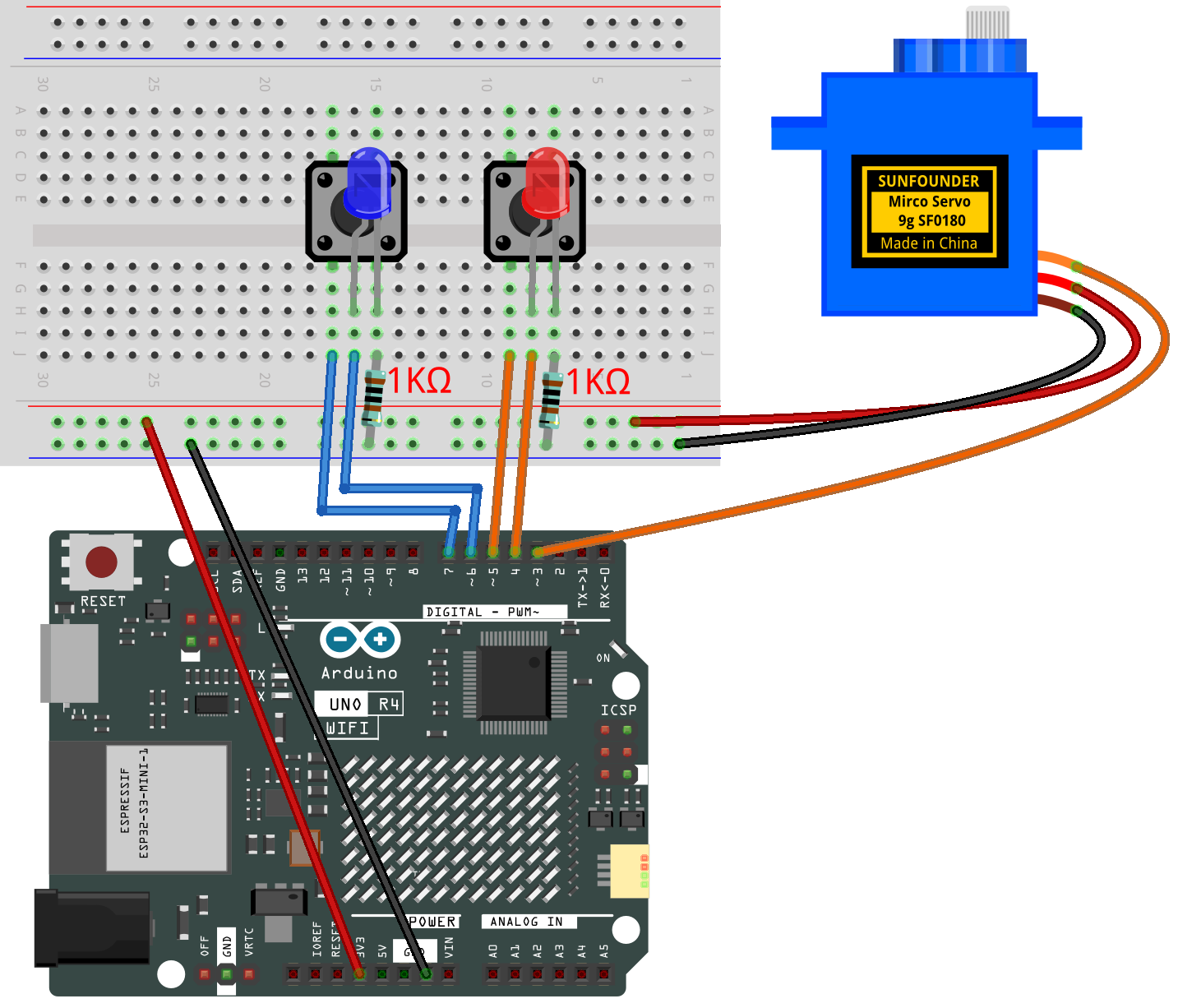
- Digital Servo Motor
- Connect to breadboard’s positive power bus.
- Connect to breadboard’s negative power bus.
- Connect to 3 on the Arduino.
- Button1
- GND: Connect to a 1kΩ resistor, then to negative power bus on the breadboard
- VCC: Connect to 7 on the Arduino.
- Button2
- GND: Connect to a 1kΩ resistor, then to negative power bus on the breadboard
- VCC: Connect to 5 on the Arduino.
- Blue LED
- Connect the LED cathode to the to a 1kΩ resistor, then to negative power bus on the breadboard, anode to 6 on the Arduino.
- Red LED
- You can copy this code into Arduino IDE.
- Don’t forget to select the board(Arduino UNO R4 Minima/WIFI) and the correct port before clicking the Upload button.
#include <Servo.h>

// --- Pin definitions ---
const int servoPin = 3;   // Servo signal wire connected to pin 3
const int redLED   = 4;   // Red LED connected to pin 4 (with resistor)
const int redBtn   = 5;   // Red button connected to pin 5
const int blueLED  = 6;   // Blue LED connected to pin 6 (with resistor)
const int blueBtn  = 7;   // Blue button connected to pin 7

Servo myServo;             // Create a Servo object
int currentAngle = 90;     // Start servo at the middle position (90°)
const int stepSize = 5;    // Servo moves 3° for each button press

// Variables to remember the last button states
bool lastRedState  = HIGH; // HIGH means not pressed (because of INPUT_PULLUP)
bool lastBlueState = HIGH;

void setup() {
  myServo.attach(servoPin);       // Attach the servo to pin 3
  myServo.write(currentAngle);    // Move servo to initial position

  pinMode(redLED, OUTPUT);        // Set LED pins as outputs
  pinMode(blueLED, OUTPUT);

  pinMode(redBtn, INPUT_PULLUP);  // Use internal pull-up resistor
  pinMode(blueBtn, INPUT_PULLUP); // Button is active LOW
}

void loop() {
  // Read current button states
  bool redPressed  = (digitalRead(redBtn)  == LOW); // LOW means pressed
  bool bluePressed = (digitalRead(blueBtn) == LOW);

  // --- Red button logic ---
  if (redPressed && lastRedState == HIGH) { // Detect new press (not held down)
    delay(50);                              // Small delay to debounce
    if (digitalRead(redBtn) == LOW) {       // Check again to confirm press
      digitalWrite(redLED, HIGH);           // Turn on red LED
      currentAngle = max(0, currentAngle - stepSize); // Move 3° toward 0°
      myServo.write(currentAngle);          // Update servo position
    }
  } else {
    digitalWrite(redLED, LOW);              // Turn off LED when not pressed
  }

  // --- Blue button logic ---
  if (bluePressed && lastBlueState == HIGH) { // Detect new press
    delay(50);                                // Debounce
    if (digitalRead(blueBtn) == LOW) {        // Confirm press
      digitalWrite(blueLED, HIGH);            // Turn on blue LED
      currentAngle = min(180, currentAngle + stepSize); // Move 3° toward 180°
      myServo.write(currentAngle);            // Update servo position
    }
  } else {
    digitalWrite(blueLED, LOW);               // Turn off LED when not pressed
  }

  // Remember button states for next loop
  lastRedState  = redPressed;
  lastBlueState = bluePressed;
}